Unlocking the Secrets of Ball Mill Diagrams for Efficient Grinding and Processing
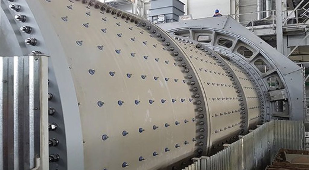
Ball mills are crucial equipment in the grinding and processing of materials in various industries, including mining, cement, chemical, and pharmaceuticals. These machines consist of a rotating cylindrical shell that uses grinding media, typically steel balls or rods, to reduce the size of raw materials to a finer consistency. Understanding the principles of ball mill diagrams is essential for optimizing their efficiency and performance in grinding processes. A ball mill diagram provides a visual representation of the components and operation of the machine, enabling engineers and operators to understand how the grinding mechanism works. It typically includes elements like the mill shell, grinding media, inlet and outlet ports, and the rotating mechanism that drives the mill. The most common type of ball mill diagram is a cross-sectional view that illustrates how materials are fed into the mill, where the grinding media comes into contact with the raw materials, and how the finer product exits the mill.

The grinding process within ball mill manufacturers is a combination of impact and abrasion forces. As the mill rotates, the grinding media moves through the material, causing it to break apart. The diagram illustrates this interaction and highlights areas where material size reduction occurs. The size and type of grinding media used play a significant role in the efficiency of the mill. Larger balls typically create more impact force, while smaller balls provide better surface area for abrasion. The diagram can also showcase the impact of the speed of rotation, where higher speeds increase the energy imparted to the grinding media, leading to faster processing but potentially causing more wear on the components. Another key aspect depicted in ball mill diagrams is the flow of materials within the mill. Feed material enters the mill through the inlet, which is typically located at one end of the cylindrical shell. The diagram shows how this material is carried through the rotating shell and gradually reduced in size by the grinding media. Understanding this material flow is vital for controlling the residence time within the mill, as longer residence times can lead to over-grinding, while shorter times may result in insufficient grinding.
Ball mill diagrams also often include detailed features such as baffles and lifters, which help to increase the movement of the grinding media and improve grinding efficiency. These components are essential in maintaining a consistent motion of the grinding media and preventing dead zones where material might accumulate and fail to be properly processed. Additionally, some diagrams may highlight various auxiliary systems, such as cooling or lubrication systems, that are integrated into the ball mill to enhance its operation. For example, cooling systems help maintain the temperature of the mill, preventing overheating that could cause damage to both the mill and the material being processed. Lubrication systems reduce friction between the moving parts, ensuring smooth operation and prolonging the life of the machine. The ball mill diagram serves as invaluable tools for understanding the inner workings of this essential equipment. By providing a clear and detailed view of the mill’s components, material flow, and grinding mechanism, these diagrams help optimize the grinding process. They enable engineers and operators to identify potential areas for improvement in efficiency, reduce wear on components, and ultimately achieve more efficient and effective grinding and processing in various industrial applications.